

2000 hyundai sonata 2.5 V6
Ok well I got myself up ****'s creek with only my hand as a pattle.
Bought this sonata that ran rough but seemed fine.
No CEL was illuminated but after i drove it home and a bit (fulfilling the drive cycle requirement) she came on solid.
Codes were
P1166
P1167
And a code unreadable by my cheap scan tool
U0d00
I tested all the o2 sensors by my blue tooth scan tool and sure enough 2 of the 4 02 sensors were reporting no change in voltage.
Got some bosh ones from o'reilly's.
Installed them and still no change in code status.
Pulled the ecu to look for bad ground path. All good. Plugged it back in and think I screwed up the common low voltage ground.
Codes
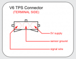
P0123
P0444
P0447
P0118
P0453
Does anyone know what wire or pin I should be checking from the ecu?
It's behind the center dash and hard to get to see where the cables are going.
Any advice on how to troubleshoot and possible soultions would be appreciated.
Ok well I got myself up ****'s creek with only my hand as a pattle.
Bought this sonata that ran rough but seemed fine.
No CEL was illuminated but after i drove it home and a bit (fulfilling the drive cycle requirement) she came on solid.
Codes were
P1166
P1167
And a code unreadable by my cheap scan tool
U0d00
I tested all the o2 sensors by my blue tooth scan tool and sure enough 2 of the 4 02 sensors were reporting no change in voltage.
Got some bosh ones from o'reilly's.
Installed them and still no change in code status.
Pulled the ecu to look for bad ground path. All good. Plugged it back in and think I screwed up the common low voltage ground.
Codes
P0123
P0444
P0447
P0118
P0453
Does anyone know what wire or pin I should be checking from the ecu?
It's behind the center dash and hard to get to see where the cables are going.
Any advice on how to troubleshoot and possible soultions would be appreciated.


")


