

I’ve wanted to add a subwoofer to my Elantra since I bought it. The “premium” sound system is sadly lacking, but I guess most factory stereos are that way. It doesn’t sound that bad up to around volume level 15, but it sounds like it falls apart at higher levels. My goal was to come up with the cleanest installation that I could by maintaining the factory look and minimize the number of permanent, irreversible changes to the car. I’m a very hands-on and visual learner, so I’ve tried to include lots of pictures. I think it makes the process pretty straight forward.
This installation was stretched out over several weekends and I wrote a little bit of this at a time so it just kept adding up. The length of this is indicative of the amount of time I have obsessed over each detail of the installation. Many things included will be obvious to anyone who has done this before, but I also wanted to document some of the techniques I used that I thought worked well and share for others to use and improve upon. Regardless of the level of detail I’ve tried to include, I wouldn’t recommend doing this yourself if you are not at least adept at working with your hands and know a thing or two about electricity and wiring. But if you have the skills and willingness to do it, you will be happy with your results because no “professional” installer will do as thorough of a job as you will do on your own car.
I don’t want to go into too much detail regarding amplifier and subwoofer selection, as that is another topic in itself, but consider if you want something small to mount under the driver’s seat, or if you’re willing to sacrifice some trunk space, something a little bigger and louder. I went with the Rockford Fosgate 150-2 amplifier and R1L-1X12 sealed subwoofer. Both of these are rated at 150 W. Crutchfield sells these at a discounted price if you buy them together in a bass package. What I like about this one, other than that it got good reviews, was that its sloped backside was designed to fit up against the seat backs to make efficient use of the space.
The main things you’ll need to buy in addition to the amp and subwoofer is an installation kit and a line output converter (LOC). The installation kit should have all the wires, connectors, fuse, tie-wraps, and other odds and ends. The kit that I ordered is below. It is advertised as 8 gauge, but it is definitely not 8 AWG, which is a standardized wire size. Leaving off that designation allows them to sell a smaller wire than you’d expect, but for my purposes with a load of 150 W, even the misrepresented 8 gauge will suffice. The speaker wire is especially small and it could be used for connecting the LOC to the external amplifier since they will not be carrying any current, but I used normal 16 AWG gauge here because I had it. I would be hesitant in using it between the amp and subwoofer because it is so small.
Neither the Elantra’s head unit nor external amplifier have RCA outputs to go to the new amplifier, so the LOC is required to convert the speaker level signals down to line level. I originally ordered the PAC SNI-35 LOC because it was cheap, but later changed my mind because I started worrying about the bass roll-off. Most factory car stereos attenuate the bass frequencies as volume increases because it stresses the inferior speakers too much trying to reproduce those frequencies. But when you add in a subwoofer that is built for playing low frequencies, you’re not left with much signal in the bass range.
I instead bought the Audio Control LC2i which is an active LOC (requires power) that is designed to restore the bass that was reduced by the factory system. It’s a bit more expensive than the cheaper, passive LOCs but all the reviews I’ve read of people who upgraded to an LC2i after having a passive LOC said it made a big difference. I figured it would be worthwhile to do it right the first time instead of upgrade it later.
The LC2i has a feature that will trigger its own remote 12 V output (the signal that tells your amplifier to turn on) whenever it detects a signal on the speaker wires. However, I’ve read that this feature is not compatible on all factory systems, so rather than take a chance and have to redo it later, I decided to bypass the LC2i’s remote trigger and wire it up directly as you normally would. There is a jumper on the LC2i that enables and disables this feature.
You could avoid the LOC issue if you buy an amplifier that accepts speaker level inputs, but then you don’t get the bass restoration. There are other products that perform a similar function, but either way you have to add another component into the system.
Just to throw it out there, it might be possible to bypass the factory external amplifier. It looks like the external amplifier gets its audio signal over copper SPDIF, but car amplifiers with SPDIF inputs are hard to come by and extremely expensive. Also, the external amp is on the car’s CAN bus (for digital communications) which makes me wonder if the amp is doing some additional processing. If that was the case, you’d also need to replace the head unit, but that replacement would have RCA outputs and you could use a normal amp. The external amp also has a signal wire labeled NAV, which makes me wonder if maybe when this signal is asserted, it lowers the volume of the music so the nav voice can be heard better. So I guess what I’m saying is, if you want to get rid of the factory amp, you’ll probably be replacing the head unit as well. These are just my guesses though.
Anyway, on to the installation.
Running the power and ground wires
The first big step is running the power wire from the battery to the trunk. I literally spent hours thinking about the cleanest way to do this, sitting upside down in the driver’s seat with my head on the floor and feet by the roof, getting out to look at the other side of the firewall under the hood, and back inside again. My approach wasn’t original, but it was in-line with my desire to hide the modifications by keeping the factory look.
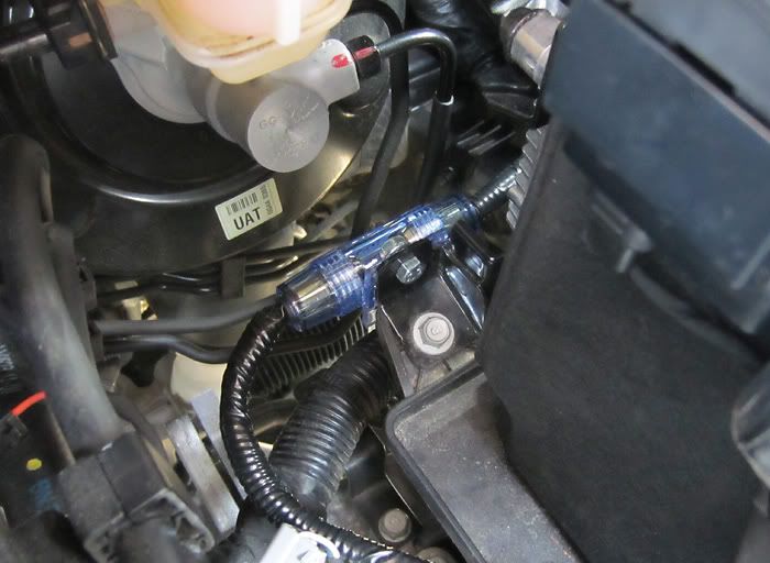
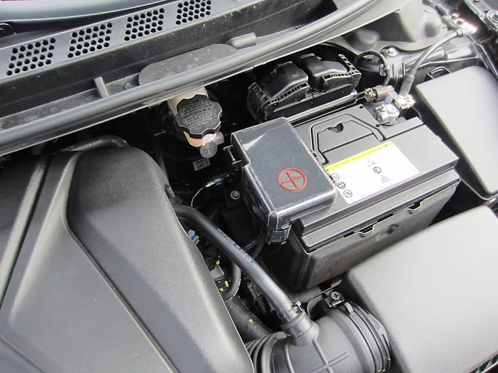
I borrowed the hole that the hood release cable is using for the power wire. The hole is lined with a rubber grommet that has a boot on the side that faces the engine bay. The actual hole in the metal is large enough for a second cable, so I used a clothes hanger to feed the power cable through the grommet. The clothes hanger ended up puncturing the boot, but otherwise went through without any snags. One thing I like about using this hole is that the battery is very close to the hole so it keeps the wire shorter, and the battery itself also hides the wire. Pull enough of the wire through to have several feet in the engine bay. Your power wire should be plenty long, so leave yourself some extra wire in case you need it when you come back to do the fuse.
![Image]()
![Image]()
Note that this was taken with the camera down in the engine bay. The hood release cable can only be seen at just the right angle when viewing from the outside.
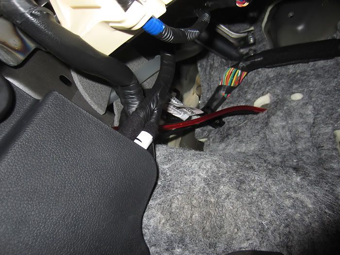
I used the clothes hanger for the next few steps that involve fishing the wire under pieces of trim. I routed the power cable behind all the factory wiring before taking it down the cowl side trim. I’d recommend going behind the factory wires as much as practical because it will make the wiring look more like it’s supposed to be there and not slapped on as a modification.
![Image]()
I removed front door scruff trim by pulling straight up on it and the wire came out the bottom of the side cowl trim. I left the center pillar trim on and fed the wire through.
![Image]()
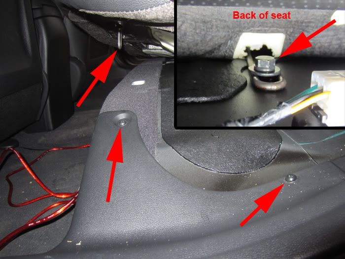
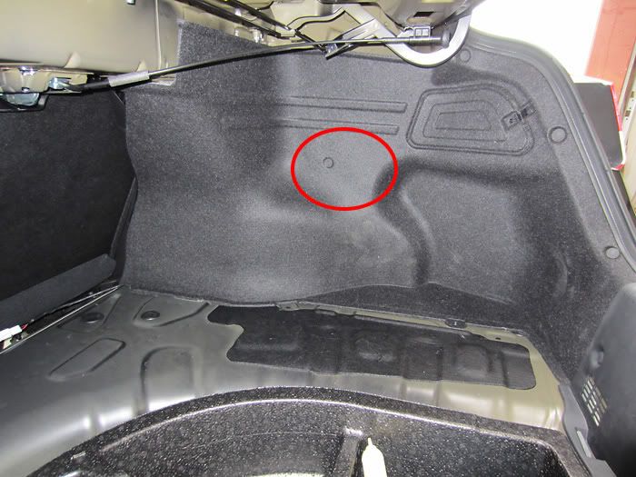
Before you can take off the rear door scruff trim, you need to remove these two screws and remove a bolt at the back of the rear seat. It is easy to access the bolt by folding the seat down and looking for it from behind. With the bolt out, you can pull up on the seat and the metal loop will pop out from the front of the seat, allowing you access to the two screws. It takes a pretty good yank to pop it out.
![Image]()
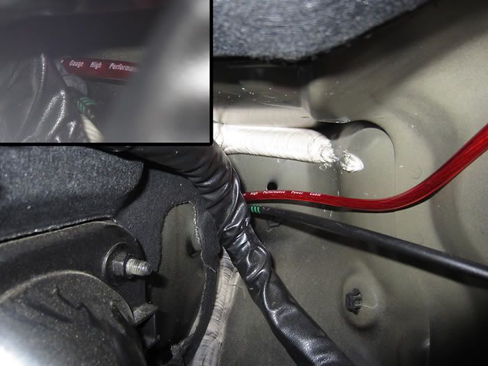
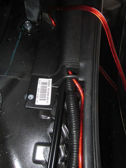
From there it’s pretty easy to feed through the rear wheel house trim and come out at the cut-out near the seat belt bolt. Then it’s a straight shot up to the trunk.
![Image]()
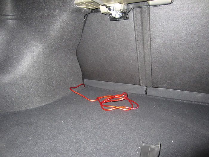
Success! Tape off the exposed end of the wire so it won’t short to ground by accident. Before doing that, you might want to set your multimeter to measure resistance and touch one lead to the exposed copper of the power wire and one to ground. This will let you know if you accidentally nicked the insulation on the wire while pulling it through.
![Image]()
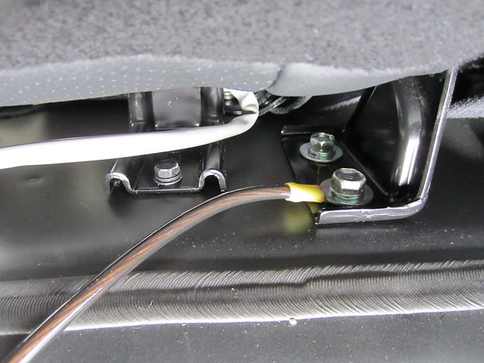
I connected the ground wire to a seat bracket bolt. It’s stainless steel and a pretty good conductor.
![Image]()
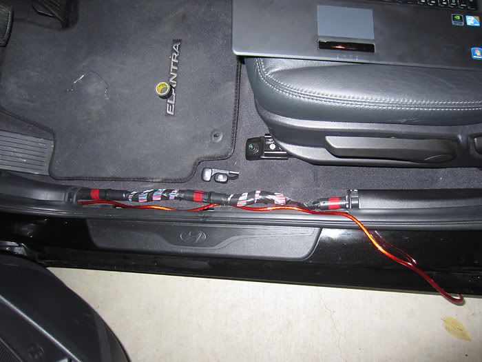
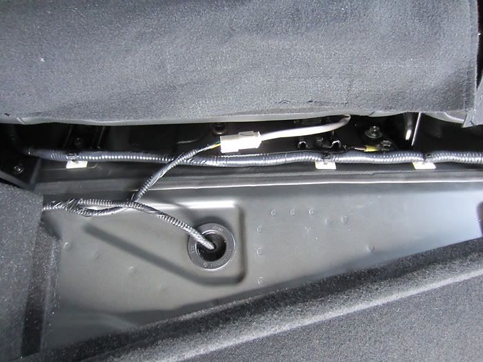
I then wrapped the power and ground wire in split loom tubing and electrical tape. The ground wire makes a 180 bend near the connector and slips inside the tubing. Once I had two wires in the tubing, I spiral wrapped the wires so that the cross sectional shape would be round which helps the tubing better keep its shape. Sticky tie downs were used to keep the tubing positioned correctly. They aren’t quite factory looking (maybe if they were black) but they serve a good purpose. They’re available at Radio Shack.
![Image]()
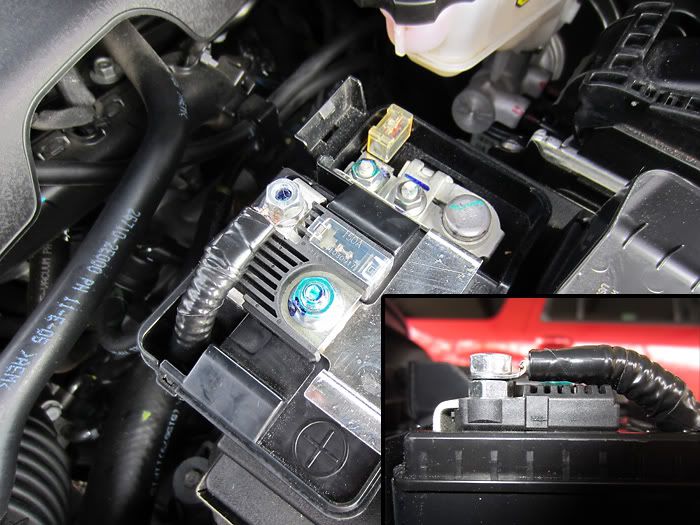
Next I connected the other end of the wire in the engine bay to the fuse and battery. There is a convenient place to mount the fuse on the bracket at the bottom of the battery. I used a 6 mm bolt (12 mm long) to mount the fuse to the bracket.
![Image]()
I played around with some different options for connecting the source side of the fuse to the battery. I ended up removing the 6 mm flange nut from the stud and replaced it with two normal 6 mm nuts with the crimp connector for the power wire between them (note: I crimped AND soldered every crimp connector in this installation). The flange nut is taller and it doesn’t line up the crimp connector as well. If it gets too tall the cover won’t close. Flange nuts are designed to not back out, and I think double nutting it serves about the same purpose so exchanging these shouldn’t create any problems. The flange nut was reused on the 6 mm bolt holding the fuse to the bracket. Once you have your wires cut to length and crimped, you can leave off the connection to the battery until you’re ready to hook up the amp.
![Image]()
The finished work disguises itself pretty well as looking like factory wiring after being enclosed in split loom tubing and wrapped in electrical tape. The fuse is a giveaway but it’s critical that it gets connected as close to the battery as possible so there’s really no hiding it.
Tapping the speaker and remote 12 V wires
The next big step is tapping into the speaker wires for the LOC and grabbing a switched 12 V signal from the external amplifier.
![Image]()
The external amplifier is located behind this piece of molded carpeting. I started by removing the floor carpeting from the trunk.
![Image]()
I then removed the rear trim piece by gently prying off the three fasteners and pulling straight up on the trim. I really developed a dislike of these fasteners while doing this installation. Every third one seemed to be stuck and took a lot of effort to remove. They are plastic so be careful not to break or mar them too bad trying to get them off. I saw that Lowes stocks these under the name “variable depth fasteners” but they are black so the colors won’t match. The dealership could probably get you some if you needed them.
![Image]()
I also removed the trim behind the passenger side rear seat. There are some more fasteners and a screw holding it on at the bottom. I left the fastener on the far right in and swung the trim out of the way. You need to remove the fastener holding the carpeting on to get it out of the way. There is another fastener holding the carpeting on further down, but it is very difficult to pop off. I left it on and swung the carpeting over inside the trunk. This step is optional, but if you don’t remove the fastener shown above, you’ll have less room to work around the external amplifier.
![Image]()
Remove the two screws at the bottom of this molded piece and pop out the fasteners and finally you should have access to the external amplifier.
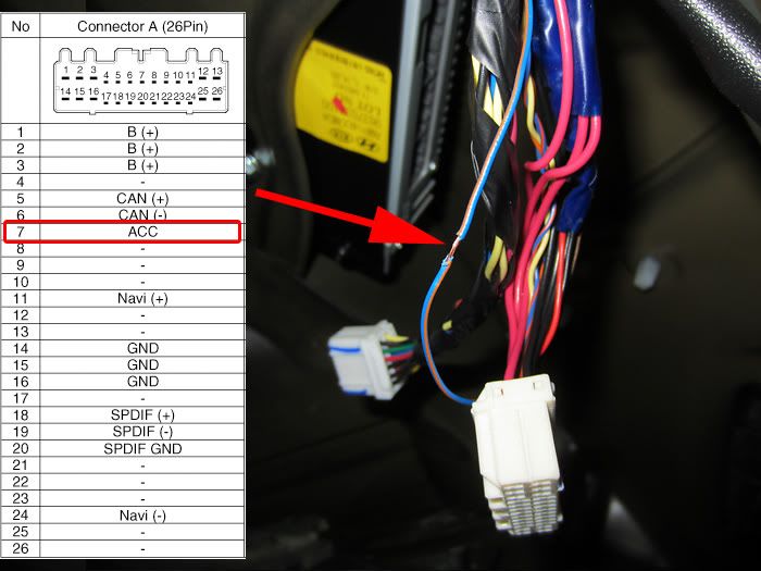
Pull off the connectors and remove the tape wrapped around these wires. You need to tap off the blue wire with a brown stripe for the switched 12 V source that will go to the LOC. Keep in mind that the connector drawings are looking at the female connector on the amplifier or the back (wire side) of the male end of the connector; however you want to look at it. As long as you know that the side of the connector that goes into the external amplifier is a mirror image of the drawing.
![Image]()
There are many ways to do taps and I prefer soldering them. I VERY CAREFULLY cut the insulation of the wire where I wanted to make the tap without cutting any of the copper. Take it slow and do a little at a time. I can’t stress that enough. Once it’s split, I pulled the insulation back in opposite directions to show more of the copper wire.
![Image]()
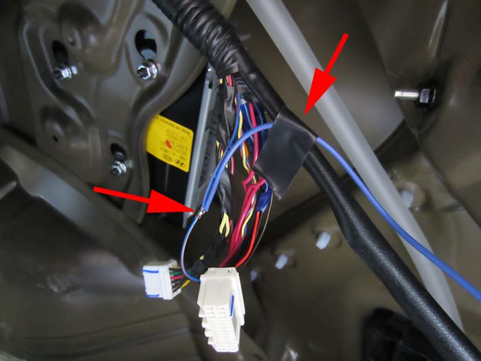
I stripped about half an inch of the blue 12 V signal wire and wrapped it around the exposed copper of the blue/brown wire. Then I carefully soldered the connection. I’d recommend bracing the blue wire with tape so that the two wires being soldered are parallel to each other. This is because the solder tends to wick back up into the wire, and if the wire was perpendicular when you soldered it, it won’t easily bend down and you’ll stress the joint.
![Image]()
I then wrapped the connection in electrical tape. I kept going past the actual solder joint to brace the two wires together and protect the joint from stressing when the cable bends or pulls.
![Image]()
I wrapped the group of wires back up in electrical tape and moved on to the other connector.
![Image]()
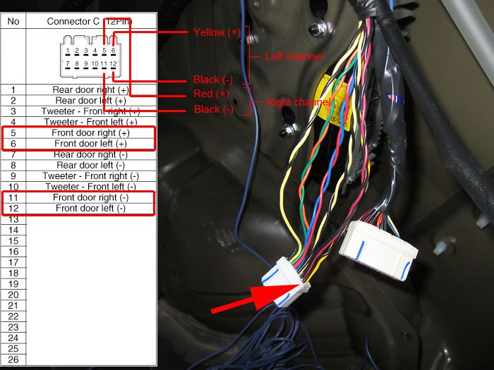
There are four taps to be made on this connector. I used the same process that I described above, but you can use whatever technique you’re familiar with. Fan out the wires and you should see the six twisted pairs. I went with tapping off the front speakers, but I don’t know if it makes any difference if you use the rear. Again, note that the connector drawing is looking at the back side of the connector (the side the wires come out of). I took my speaker wire and connected to +/- of the left channel with one wire and +/- of the right channel with the other wire. Don’t forget to label each individual wire as you solder it. Polarity matters.
![Image]()
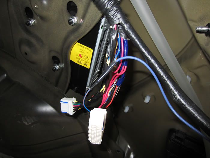
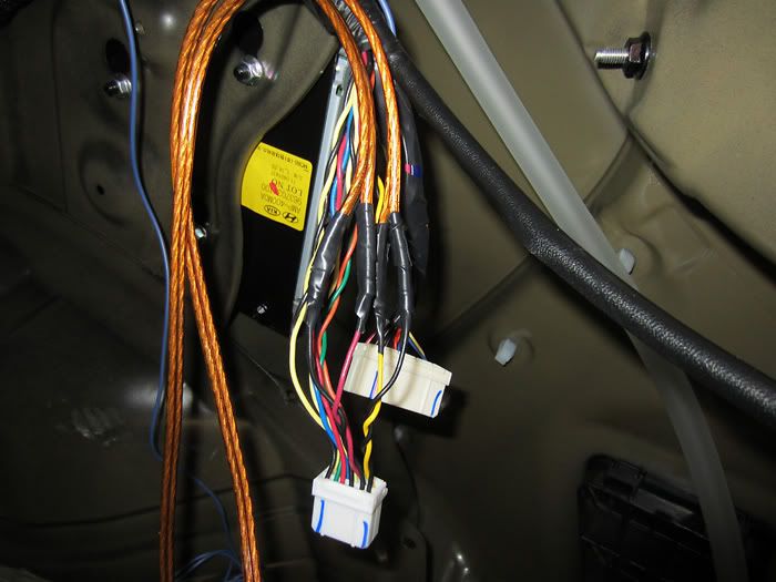
Here’s what mine looked like when it was all done. Then I bundled the wires up in electrical tape and plugged the connectors back in. I wrapped the two speaker wires and 12 V signal wire in 3/8” split loom tubing and wrapped the tubing in electrical tape for the entire length. This is the step (tapping the wires) that I’d consider the most irreversible of what I’ve done, but at least it can be hidden in electrical tape and tucked away behind the molded carpeting so no one would notice.
![Image]()
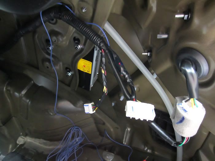
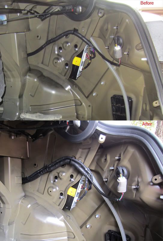
Before and after shot. Looks like a factory job.
![Image]()
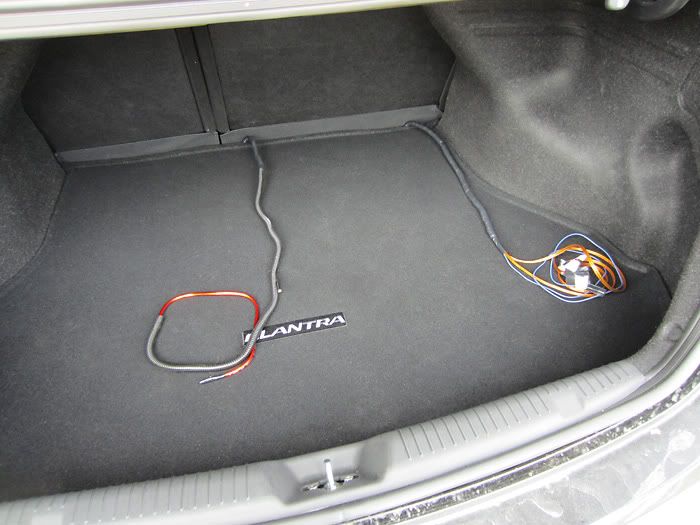
Finally ready for the amplifier and subwoofer to be installed.
[continued below]
This installation was stretched out over several weekends and I wrote a little bit of this at a time so it just kept adding up. The length of this is indicative of the amount of time I have obsessed over each detail of the installation. Many things included will be obvious to anyone who has done this before, but I also wanted to document some of the techniques I used that I thought worked well and share for others to use and improve upon. Regardless of the level of detail I’ve tried to include, I wouldn’t recommend doing this yourself if you are not at least adept at working with your hands and know a thing or two about electricity and wiring. But if you have the skills and willingness to do it, you will be happy with your results because no “professional” installer will do as thorough of a job as you will do on your own car.
I don’t want to go into too much detail regarding amplifier and subwoofer selection, as that is another topic in itself, but consider if you want something small to mount under the driver’s seat, or if you’re willing to sacrifice some trunk space, something a little bigger and louder. I went with the Rockford Fosgate 150-2 amplifier and R1L-1X12 sealed subwoofer. Both of these are rated at 150 W. Crutchfield sells these at a discounted price if you buy them together in a bass package. What I like about this one, other than that it got good reviews, was that its sloped backside was designed to fit up against the seat backs to make efficient use of the space.
The main things you’ll need to buy in addition to the amp and subwoofer is an installation kit and a line output converter (LOC). The installation kit should have all the wires, connectors, fuse, tie-wraps, and other odds and ends. The kit that I ordered is below. It is advertised as 8 gauge, but it is definitely not 8 AWG, which is a standardized wire size. Leaving off that designation allows them to sell a smaller wire than you’d expect, but for my purposes with a load of 150 W, even the misrepresented 8 gauge will suffice. The speaker wire is especially small and it could be used for connecting the LOC to the external amplifier since they will not be carrying any current, but I used normal 16 AWG gauge here because I had it. I would be hesitant in using it between the amp and subwoofer because it is so small.
Neither the Elantra’s head unit nor external amplifier have RCA outputs to go to the new amplifier, so the LOC is required to convert the speaker level signals down to line level. I originally ordered the PAC SNI-35 LOC because it was cheap, but later changed my mind because I started worrying about the bass roll-off. Most factory car stereos attenuate the bass frequencies as volume increases because it stresses the inferior speakers too much trying to reproduce those frequencies. But when you add in a subwoofer that is built for playing low frequencies, you’re not left with much signal in the bass range.
I instead bought the Audio Control LC2i which is an active LOC (requires power) that is designed to restore the bass that was reduced by the factory system. It’s a bit more expensive than the cheaper, passive LOCs but all the reviews I’ve read of people who upgraded to an LC2i after having a passive LOC said it made a big difference. I figured it would be worthwhile to do it right the first time instead of upgrade it later.
The LC2i has a feature that will trigger its own remote 12 V output (the signal that tells your amplifier to turn on) whenever it detects a signal on the speaker wires. However, I’ve read that this feature is not compatible on all factory systems, so rather than take a chance and have to redo it later, I decided to bypass the LC2i’s remote trigger and wire it up directly as you normally would. There is a jumper on the LC2i that enables and disables this feature.
You could avoid the LOC issue if you buy an amplifier that accepts speaker level inputs, but then you don’t get the bass restoration. There are other products that perform a similar function, but either way you have to add another component into the system.
Just to throw it out there, it might be possible to bypass the factory external amplifier. It looks like the external amplifier gets its audio signal over copper SPDIF, but car amplifiers with SPDIF inputs are hard to come by and extremely expensive. Also, the external amp is on the car’s CAN bus (for digital communications) which makes me wonder if the amp is doing some additional processing. If that was the case, you’d also need to replace the head unit, but that replacement would have RCA outputs and you could use a normal amp. The external amp also has a signal wire labeled NAV, which makes me wonder if maybe when this signal is asserted, it lowers the volume of the music so the nav voice can be heard better. So I guess what I’m saying is, if you want to get rid of the factory amp, you’ll probably be replacing the head unit as well. These are just my guesses though.
Anyway, on to the installation.
Running the power and ground wires
The first big step is running the power wire from the battery to the trunk. I literally spent hours thinking about the cleanest way to do this, sitting upside down in the driver’s seat with my head on the floor and feet by the roof, getting out to look at the other side of the firewall under the hood, and back inside again. My approach wasn’t original, but it was in-line with my desire to hide the modifications by keeping the factory look.
I borrowed the hole that the hood release cable is using for the power wire. The hole is lined with a rubber grommet that has a boot on the side that faces the engine bay. The actual hole in the metal is large enough for a second cable, so I used a clothes hanger to feed the power cable through the grommet. The clothes hanger ended up puncturing the boot, but otherwise went through without any snags. One thing I like about using this hole is that the battery is very close to the hole so it keeps the wire shorter, and the battery itself also hides the wire. Pull enough of the wire through to have several feet in the engine bay. Your power wire should be plenty long, so leave yourself some extra wire in case you need it when you come back to do the fuse.
Note that this was taken with the camera down in the engine bay. The hood release cable can only be seen at just the right angle when viewing from the outside.
I used the clothes hanger for the next few steps that involve fishing the wire under pieces of trim. I routed the power cable behind all the factory wiring before taking it down the cowl side trim. I’d recommend going behind the factory wires as much as practical because it will make the wiring look more like it’s supposed to be there and not slapped on as a modification.
I removed front door scruff trim by pulling straight up on it and the wire came out the bottom of the side cowl trim. I left the center pillar trim on and fed the wire through.
Before you can take off the rear door scruff trim, you need to remove these two screws and remove a bolt at the back of the rear seat. It is easy to access the bolt by folding the seat down and looking for it from behind. With the bolt out, you can pull up on the seat and the metal loop will pop out from the front of the seat, allowing you access to the two screws. It takes a pretty good yank to pop it out.
From there it’s pretty easy to feed through the rear wheel house trim and come out at the cut-out near the seat belt bolt. Then it’s a straight shot up to the trunk.
Success! Tape off the exposed end of the wire so it won’t short to ground by accident. Before doing that, you might want to set your multimeter to measure resistance and touch one lead to the exposed copper of the power wire and one to ground. This will let you know if you accidentally nicked the insulation on the wire while pulling it through.
I connected the ground wire to a seat bracket bolt. It’s stainless steel and a pretty good conductor.
I then wrapped the power and ground wire in split loom tubing and electrical tape. The ground wire makes a 180 bend near the connector and slips inside the tubing. Once I had two wires in the tubing, I spiral wrapped the wires so that the cross sectional shape would be round which helps the tubing better keep its shape. Sticky tie downs were used to keep the tubing positioned correctly. They aren’t quite factory looking (maybe if they were black) but they serve a good purpose. They’re available at Radio Shack.
Next I connected the other end of the wire in the engine bay to the fuse and battery. There is a convenient place to mount the fuse on the bracket at the bottom of the battery. I used a 6 mm bolt (12 mm long) to mount the fuse to the bracket.
I played around with some different options for connecting the source side of the fuse to the battery. I ended up removing the 6 mm flange nut from the stud and replaced it with two normal 6 mm nuts with the crimp connector for the power wire between them (note: I crimped AND soldered every crimp connector in this installation). The flange nut is taller and it doesn’t line up the crimp connector as well. If it gets too tall the cover won’t close. Flange nuts are designed to not back out, and I think double nutting it serves about the same purpose so exchanging these shouldn’t create any problems. The flange nut was reused on the 6 mm bolt holding the fuse to the bracket. Once you have your wires cut to length and crimped, you can leave off the connection to the battery until you’re ready to hook up the amp.
The finished work disguises itself pretty well as looking like factory wiring after being enclosed in split loom tubing and wrapped in electrical tape. The fuse is a giveaway but it’s critical that it gets connected as close to the battery as possible so there’s really no hiding it.
Tapping the speaker and remote 12 V wires
The next big step is tapping into the speaker wires for the LOC and grabbing a switched 12 V signal from the external amplifier.
The external amplifier is located behind this piece of molded carpeting. I started by removing the floor carpeting from the trunk.
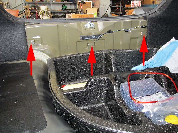
I then removed the rear trim piece by gently prying off the three fasteners and pulling straight up on the trim. I really developed a dislike of these fasteners while doing this installation. Every third one seemed to be stuck and took a lot of effort to remove. They are plastic so be careful not to break or mar them too bad trying to get them off. I saw that Lowes stocks these under the name “variable depth fasteners” but they are black so the colors won’t match. The dealership could probably get you some if you needed them.
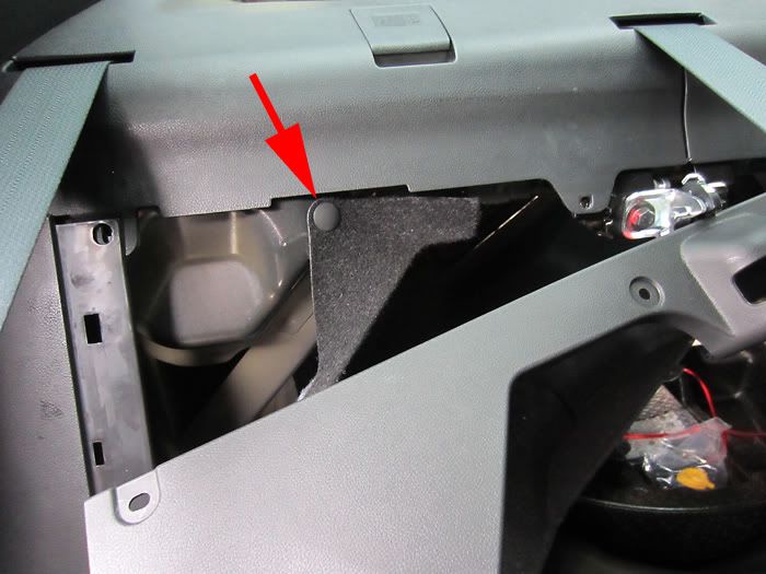
I also removed the trim behind the passenger side rear seat. There are some more fasteners and a screw holding it on at the bottom. I left the fastener on the far right in and swung the trim out of the way. You need to remove the fastener holding the carpeting on to get it out of the way. There is another fastener holding the carpeting on further down, but it is very difficult to pop off. I left it on and swung the carpeting over inside the trunk. This step is optional, but if you don’t remove the fastener shown above, you’ll have less room to work around the external amplifier.
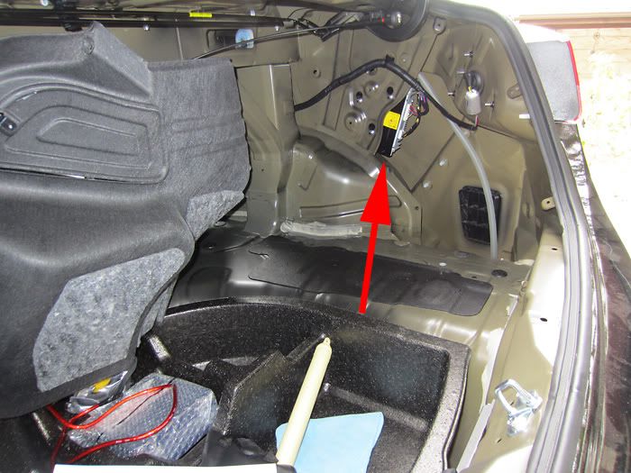
Remove the two screws at the bottom of this molded piece and pop out the fasteners and finally you should have access to the external amplifier.
Pull off the connectors and remove the tape wrapped around these wires. You need to tap off the blue wire with a brown stripe for the switched 12 V source that will go to the LOC. Keep in mind that the connector drawings are looking at the female connector on the amplifier or the back (wire side) of the male end of the connector; however you want to look at it. As long as you know that the side of the connector that goes into the external amplifier is a mirror image of the drawing.
There are many ways to do taps and I prefer soldering them. I VERY CAREFULLY cut the insulation of the wire where I wanted to make the tap without cutting any of the copper. Take it slow and do a little at a time. I can’t stress that enough. Once it’s split, I pulled the insulation back in opposite directions to show more of the copper wire.
I stripped about half an inch of the blue 12 V signal wire and wrapped it around the exposed copper of the blue/brown wire. Then I carefully soldered the connection. I’d recommend bracing the blue wire with tape so that the two wires being soldered are parallel to each other. This is because the solder tends to wick back up into the wire, and if the wire was perpendicular when you soldered it, it won’t easily bend down and you’ll stress the joint.
I then wrapped the connection in electrical tape. I kept going past the actual solder joint to brace the two wires together and protect the joint from stressing when the cable bends or pulls.
I wrapped the group of wires back up in electrical tape and moved on to the other connector.
There are four taps to be made on this connector. I used the same process that I described above, but you can use whatever technique you’re familiar with. Fan out the wires and you should see the six twisted pairs. I went with tapping off the front speakers, but I don’t know if it makes any difference if you use the rear. Again, note that the connector drawing is looking at the back side of the connector (the side the wires come out of). I took my speaker wire and connected to +/- of the left channel with one wire and +/- of the right channel with the other wire. Don’t forget to label each individual wire as you solder it. Polarity matters.
Here’s what mine looked like when it was all done. Then I bundled the wires up in electrical tape and plugged the connectors back in. I wrapped the two speaker wires and 12 V signal wire in 3/8” split loom tubing and wrapped the tubing in electrical tape for the entire length. This is the step (tapping the wires) that I’d consider the most irreversible of what I’ve done, but at least it can be hidden in electrical tape and tucked away behind the molded carpeting so no one would notice.
Before and after shot. Looks like a factory job.
Finally ready for the amplifier and subwoofer to be installed.
[continued below]


")


